Case study
Twin-Turbo Manifold Packaging
Working out where the turbos and manifolds could physically go in a tight engine bay, then designing geometry that suited the result.
- 3D Scanning
- Packaging
- CAD Design
- Fabrication
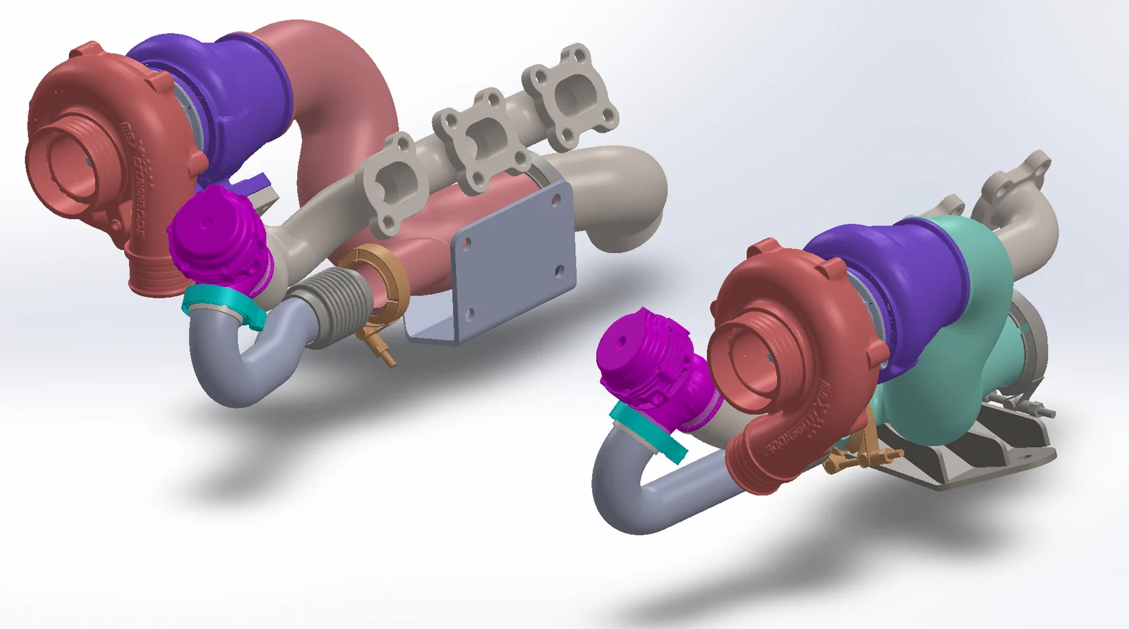
Scanned component geometry combined with custom CAD to resolve the turbo, manifold and plumbing arrangement as one assembly.
The problem
There was very little free space in the engine bay, and turbo position, manifold routing and clearance to everything else were all tied together. Trying positions physically would have meant a lot of trial fitting.
The approach
We scanned the engine bay and the components involved, then positioned the turbos in CAD to test options against the real geometry. Once the positions worked, the manifold and connecting geometry were modelled to suit, with clearances checked before anything was cut.
The result
Turbo positions and manifold geometry were resolved in CAD first. Each finished manifold was 3D printed in 316L stainless steel in two parts, then TIG welded together.
Design & development
From geometry to physical parts
Project photographs and CAD views from the development process.
- 01
Manifold design
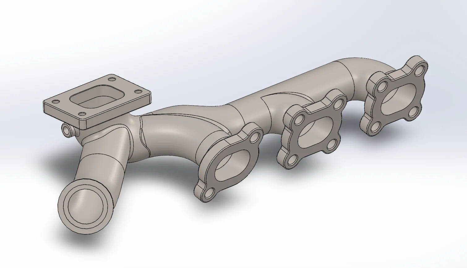
Manifold routing and interfaces developed within the combined scan and CAD assembly shown above.
- 02
Printed & TIG welded
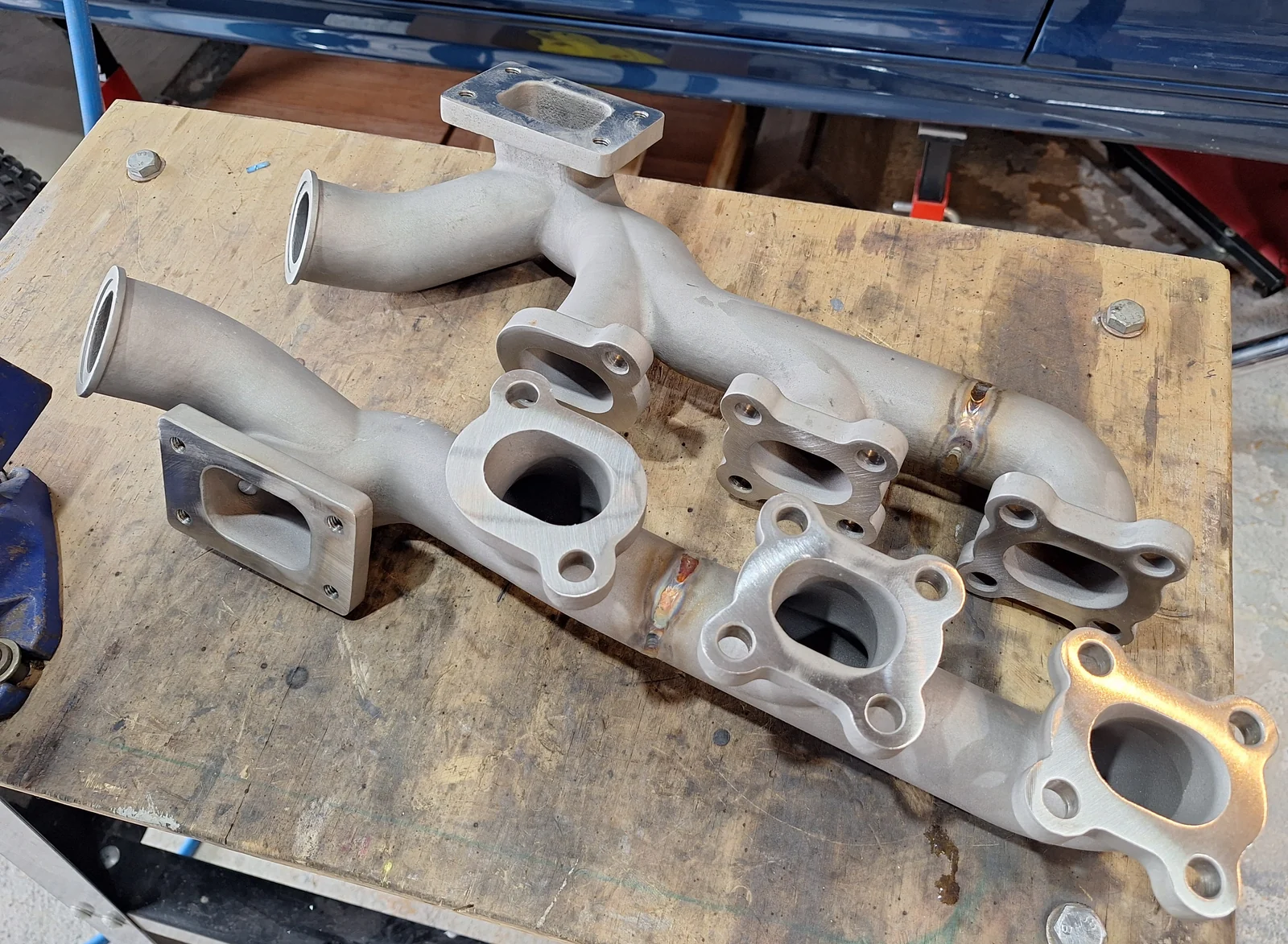
Each manifold was 3D printed in 316L stainless steel in two parts, then TIG welded together to produce the finished component.
Other projects
Brake Package & Caliper Mounting
Scanning existing hub and upright geometry to design a caliper mounting bracket that fits the brake package around what was already there.
Dry-Sump Oil Pan
A dry-sump pan designed around restricted space and several mechanical interfaces that all had to be respected at once.
Got something in mind?
Send us a few photos and tell us what you're trying to achieve.