Case study
Dry-Sump Oil Pan
A dry-sump pan designed around restricted space and several mechanical interfaces that all had to be respected at once.
- 3D Scanning
- Reverse Engineering
- CAD Design
- Packaging
The problem
The pan had to clear what was underneath the engine, seal to the block, and suit the pickups and plumbing, all within a shallow space. Each interface constrained the others, so the design could not be worked out from measurements alone.
The approach
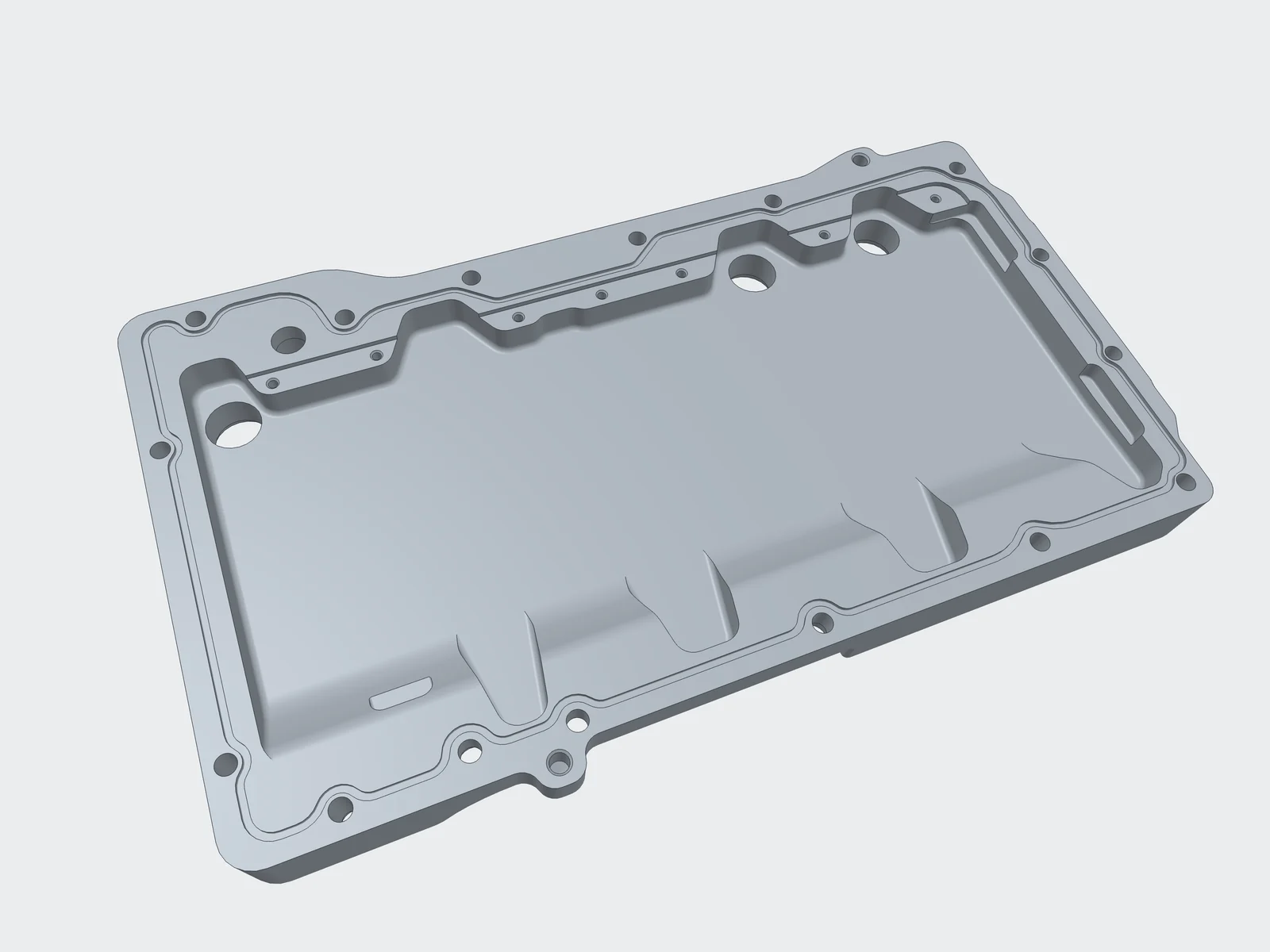
We captured the block face, surrounding structure and the space available, then rebuilt the interfaces as clean CAD geometry. The pan was designed against that model so the sealing face, fixing pattern, pickup positions and ground clearance could all be assessed together rather than one at a time.
The result
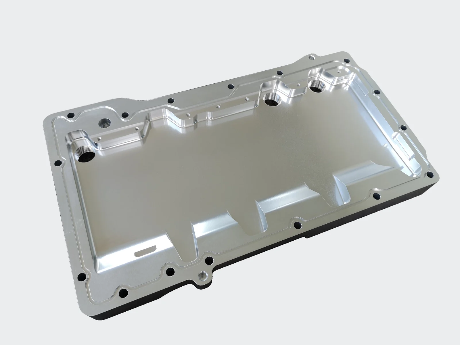
A manufactured dry-sump pan developed around the required space and mechanical interfaces, with its key features carried through from CAD to metal.
Design & development
From geometry to physical parts
Project photographs and CAD views from the development process.
- 01
CAD design
The pan geometry, with the sealing face, fixing pattern and internal features resolved in CAD.
- 02
Manufactured part
The manufactured pan, with the internal geometry and machined sealing groove visible.
- 03
Opposite face
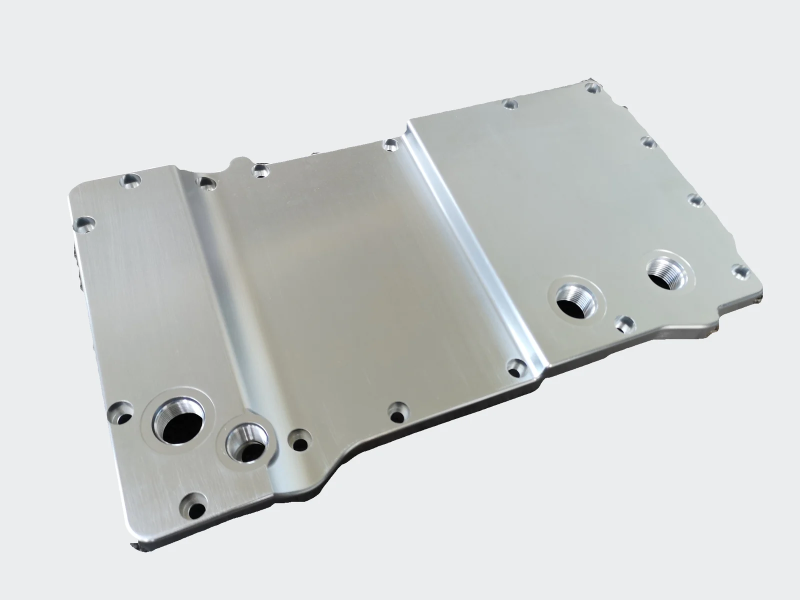
The opposite face reveals the shallow profile and threaded connections.
Other projects
Brake Package & Caliper Mounting
Scanning existing hub and upright geometry to design a caliper mounting bracket that fits the brake package around what was already there.
Twin-Turbo Manifold Packaging
Working out where the turbos and manifolds could physically go in a tight engine bay, then designing geometry that suited the result.
Got something in mind?
Send us a few photos and tell us what you're trying to achieve.